

Series AS
Features include:
- Finger-safe terminals designed to accept bare wire, ferrules, spade or ring lugs
- Enclosed coils 50-750 VA to protect against moisture, dirt, dust and industrial contaminants
- Primary Voltage 120 x 240
- Secondary Voltage 24V
- Frequency 50/60 Hz
- Constructed with high quality silicon steel laminates
- Highest quality copper magnetic wire ensures efficient operation
- Labeled with complete wiring diagram
- Two parallel jumper links come standard with all transformers which can be wired for dual primary voltages
- Heavy duty steel mounting plate with slotted mounting feet for easy and flexible installation
- Mounting adapter for fuse blocks
- Fusing options available in kits or factory installed
- Meets or exceeds, UL, CE, CSA,
NEMA, ANSI,
and OSHA standards
AS SERIES
|
AS Series 50 VA, 50/60 Hz | |
| PRI | SEC |
| 120 x 240 | 24 |
| Part # MPC2-1B050ASU | |
|
AS Series 75 VA, 50/60 Hz | |
| PRI | SEC |
| 120 x 240 | 24 |
| Part # MPC2-1B075ASU | |
|
AS Series 100 VA, 50/60 Hz | |
| PRI | SEC |
| 120 x 240 | 24 |
| Part # MPC2-1B100ASU | |
|
AS Series 150 VA, 50/60 Hz | |
| PRI | SEC |
| 120 x 240 | 24 |
| Part # MPC2-2B150ASU | |
|
AS Series 200 VA, 50/60 Hz | |
| PRI | SEC |
| 120 x 240 | 24 |
| Part # MPC2-2B200ASU | |
|
AS Series 250 VA, 50/60 Hz | |
| PRI | SEC |
| 120 x 240 | 24 |
| Part # MPC2-2B250BSU | |
|
AS Series 300 VA, 50/60 Hz | |
| PRI | SEC |
| 120 x 240 | 24 |
| Part # MPC2-2B300ASU | |
|
AS Series 350 VA, 50/60 Hz | |
| PRI | SEC |
| 120 x 240 | 24 |
| Part # MPC2-2B350ASU | |
|
AS Series 750 VA, 50/60 Hz | |
| PRI | SEC |
| 120 x 240 | 24 |
| Part # MPC2-2B750ASU-** | |
PDF Downloads

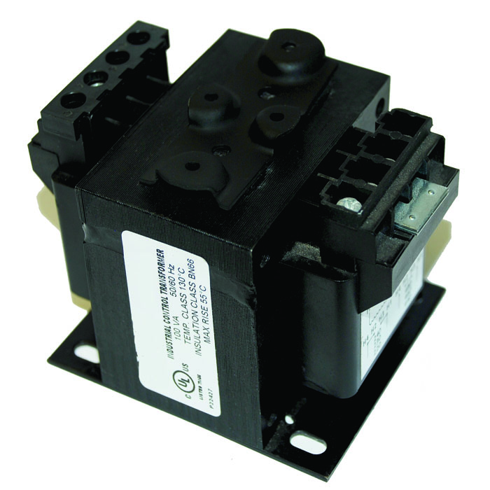
AS SERIES
PRI SEC
120 X
240
24
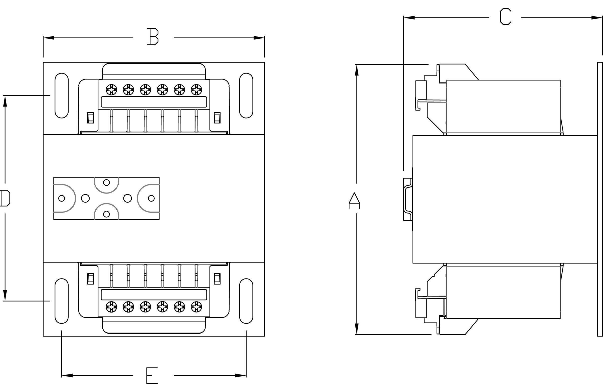
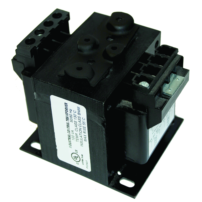
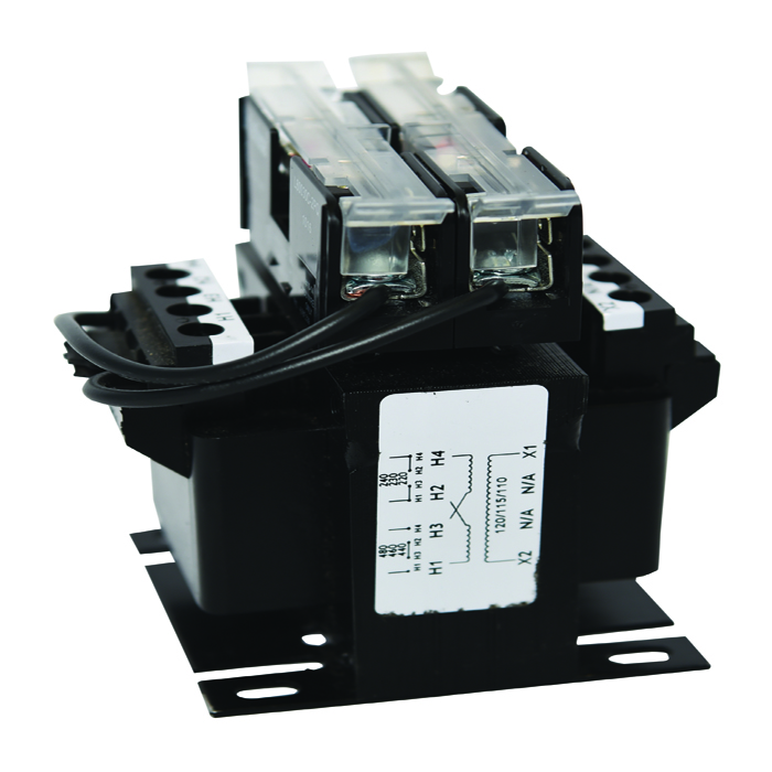
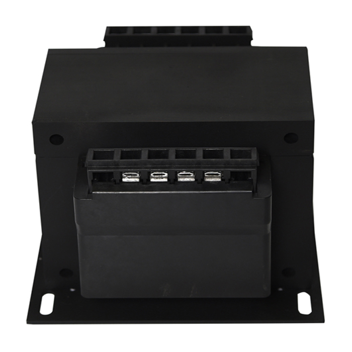
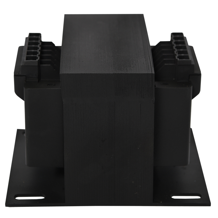
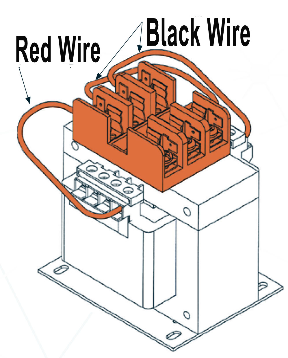
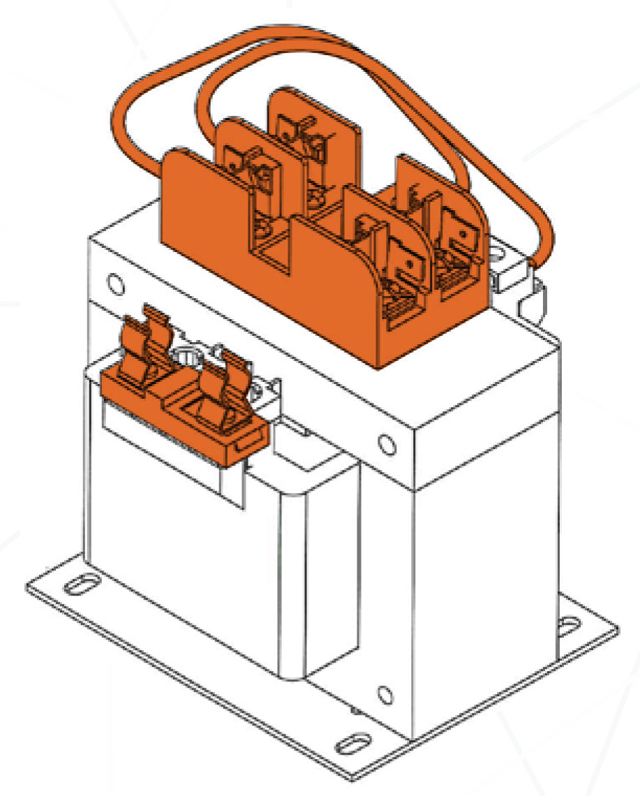
Image is a general representation of a typical MPC Transformer without fusing accessories or jumper links. Transformers 50VA - 350 VA have 4 terminals per side and units 500Va and higher have 6 terminals per side.
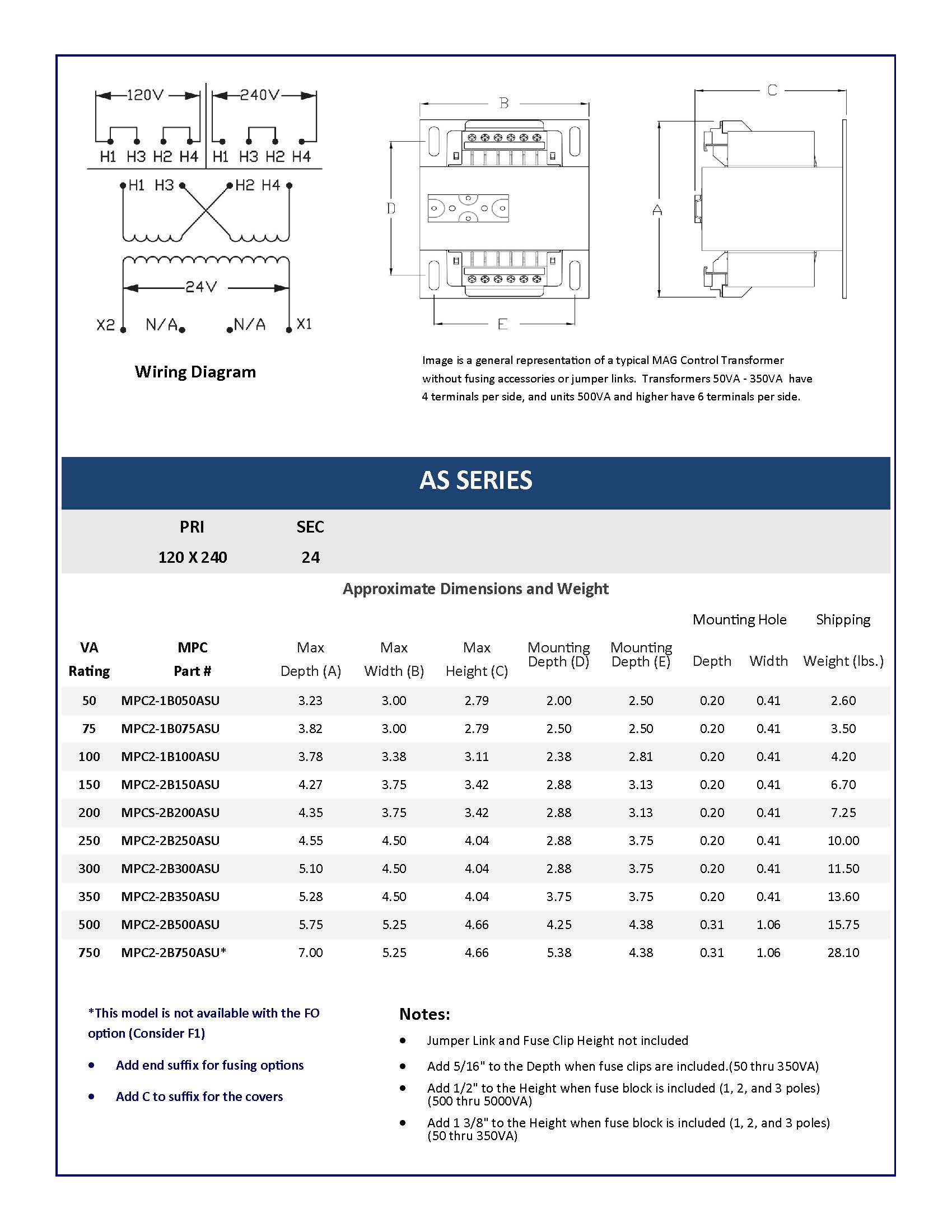
Wiring Diagram
| Approximate Dimensions and Weight | |||||||||
| Mounting Hole | Shipping | ||||||||
| VA Rating |
MPC Model # |
Max Depth (A) |
Max Width (B) |
Max Height (C) |
Mounting Depth (D) |
Mounting Depth (E) |
Depth | Width | Weight (lbs.) |
| 50 | MPC2-1B050ASU | 3.32 | 3.00 | 2.79 | 2.00 | 2.50 | 0.20 | 0.41 | 2.60 |
| 75 | MPC2-1B075ASU | 3.82 | 3.00 | 2.79 | 2.50 | 2.50 | 0.20 | 0.41 | 3.50 |
| 100 | MPC2-1B100ASU | 3.78 | 3.38 | 3.11 | 2.38 | 2.81 | 0.20 | 0.41 | 4.20 |
| 150 | MPC2-2B150ASU | 4.27 | 3.75 | 3.42 | 2.88 | 3.13 | 0.20 | 0.41 | 6.70 |
| 200 | MPC2-2B200ASU | 4.35 | 3.75 | 3.42 | 2.88 | 3.13 | 0.20 | 0.41 | 7.25 |
| 250 | MPC2-2B250ASU | 4.55 | 4.50 | 4.04 | 2.88 | 3.75 | 0.20 | 0.41 | 10.00 |
| 300 | MPC2-2B300ASU | 5.10 | 4.50 | 4.04 | 2.88 | 3.75 | 0.20 | 0.41 | 11.50 |
| 350 | MPC2-2B350ASU | 5.28 | 4.50 | 4.04 | 3.75 | 3.75 | 0.20 | 0.41 | 13.60 |
| 500 | MPC2-2B500ASU | 5.75 | 5.25 | 4.66 | 4.25 | 4.38 | 0.31 | 1.06 | 15.75 |
| 750 | MPC2-2B750ASU-** | 7.00 | 5.25 | 4.66 | 5.38 | 4.38 | 0.31 | 1.06 | 28.10 |
**This model is not available with the FO option (Consider F1) | |||||||||
| - Add end suffix for fusing options | |||||||||
| -Add C to suffix for the covers | |||||||||
Fusing Options
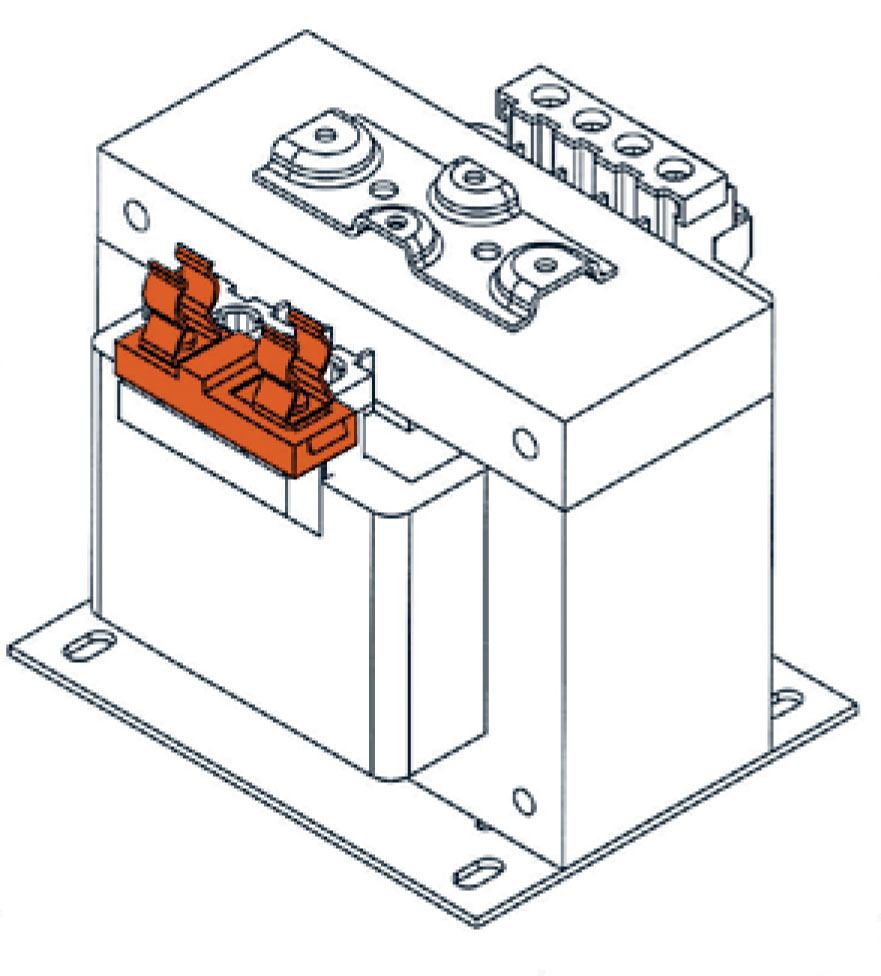
Option FO
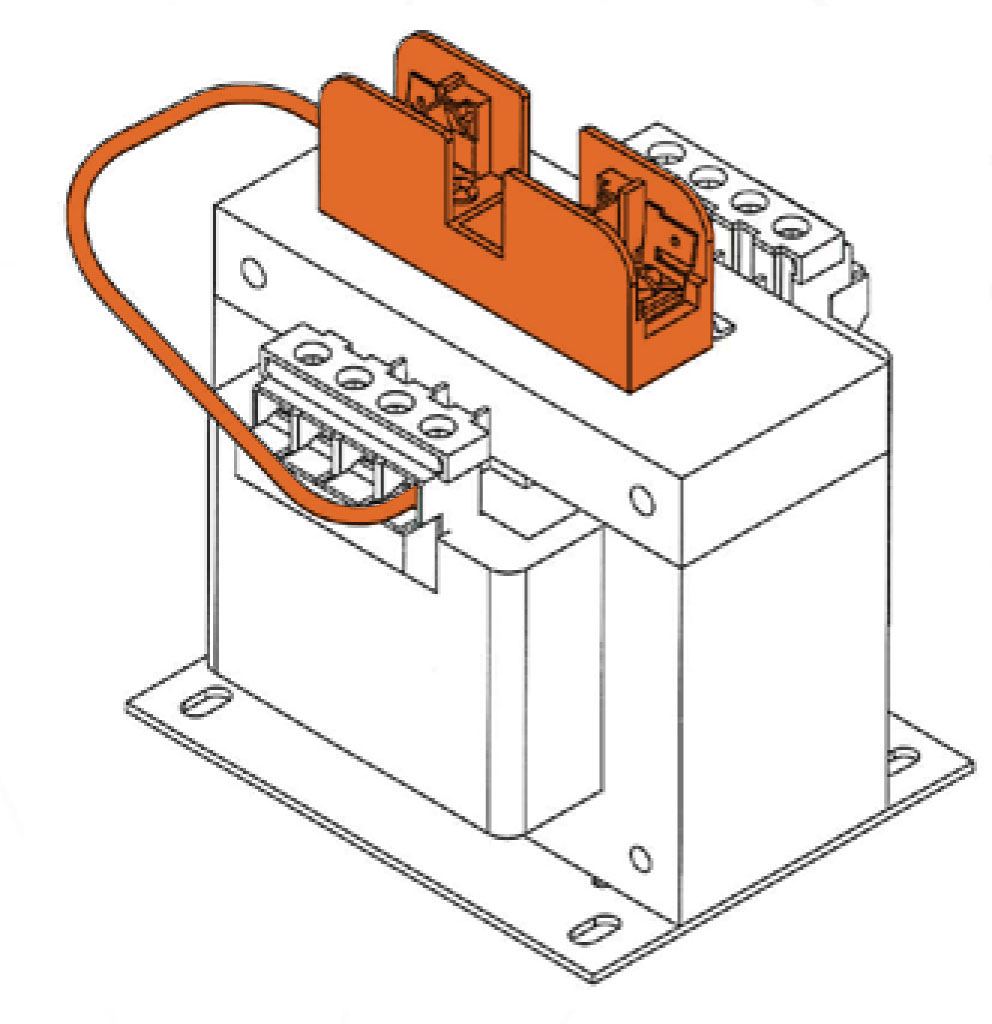
Option F1
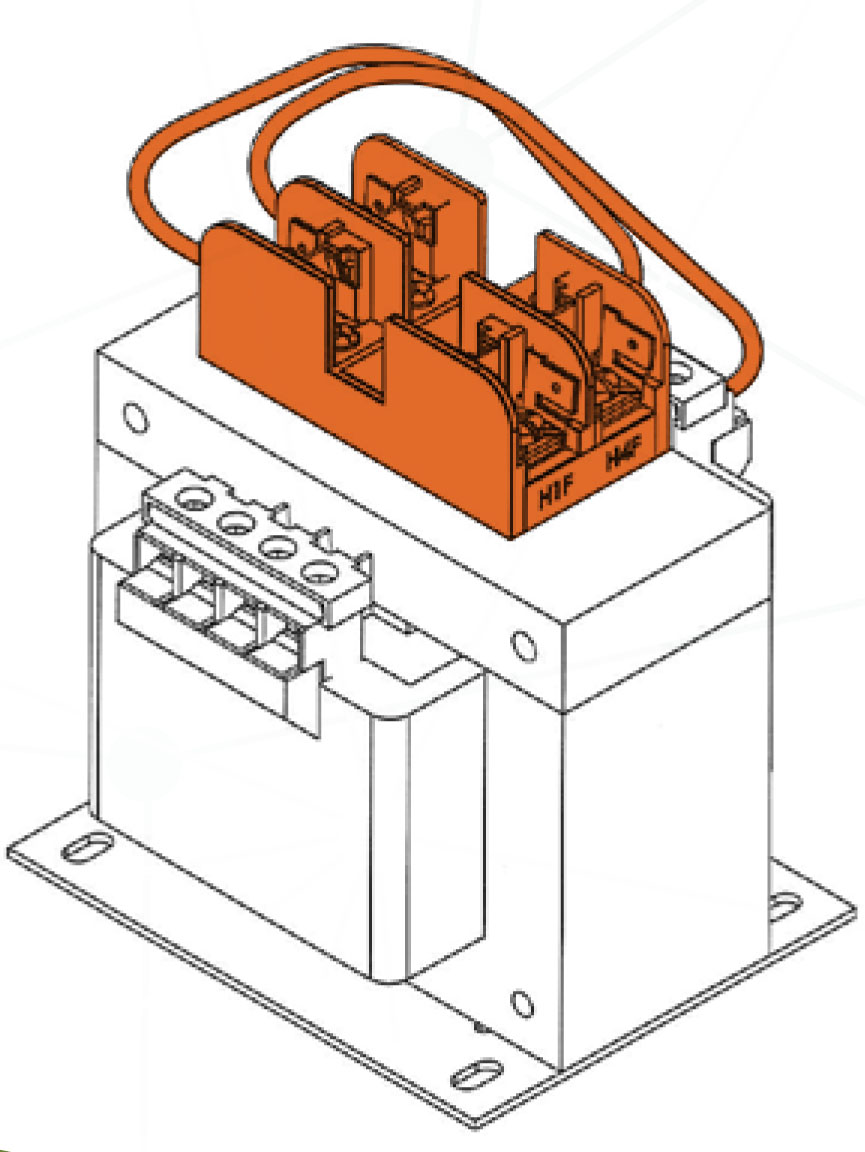
Option F2
Option F3
Option F4
|
Add to (MPC Part #) |
MPC Part (Ordered Separately) |
Fusing Options |
| C | MCP2-ACC-PFBCVK | PRI Fuse Cover Kit with puller |
| C | MCP2-ACC-SFBCVK | Secondary Fuse Cover Kit |
| FO | MCP2-ACC-FOB | Kit Secondary Fuse Clips (45VA-750VA) |
| FO | MCP2-ACC-FOH | Kit Secondard Fuse Clips (1KVA-5KVA) |
| F1 | MCP2-ACC-F1 | Kit Sec Fuse Block 1 - Midget |
| F2 | MCP2-ACC-F2 | Kit PRI Fuse Block 2 - CC |
| F3 | MCP2-ACC-F3 | Kit Fuse Block 2 - CC & 1 - Midget |
| F4 | MCP2-ACC-F4 | Kit Fuse Block 2 - CC & Clips |